IBM
The case for a leaf-spine data center topology
Three-layer network designs are last season's topology. The leaf-spine model is coming in hot, but can the advantages made data center designers forget about the weaknesses?

Three-layer designs are falling out of favor in modern data center networks, despite their ubiquity and familiarity. What's taking over? Leaf-spine topologies.
As organizations seek to maximize the utility and utilization of their respective data centers, there's been increased scrutiny of mainstream network topologies. "Topology" is the way in which network devices are interconnected, forming a pathway that hosts follow to communicate with each other.
The standard network data center topology was a three-layer architecture: the access layer, where users connect to the network; the aggregation layer, where access switches intersect; and the core, where aggregation switches interconnect to each other and to networks outside of the data center.
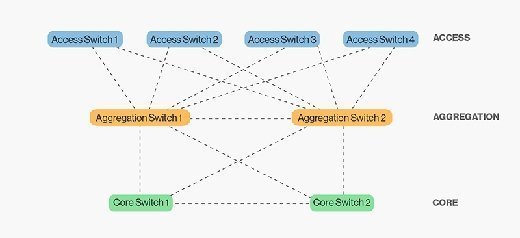
The design of this model provides a predictable foundation for a data center network. Physically scaling the three-layer model involves identifying port density requirements and purchasing an appropriate number of switches for each layer. Structured cabling requirements are also predictable, as interconnecting between layers is done the same way across the data center. Therefore, growing a three-layer network is as simple as ordering more switches and running more cable against well-known capital and operational cost numbers.
Why three-layer falls short
Yet there are many reasons that network architects explore new data center topologies.
Perhaps the most significant is the change in data center traffic patterns. Most network traffic moves along a north-south line -- hosts are communicating with hosts from other segments of the network. North-south traffic flows down the model for routing service, and then back up to reach its destination. Meanwhile, hosts within the same network segment usually connect to the same switch, keeping their traffic off the network interconnection points.
However, in modern data centers, compute and storage infrastructures alterations change the predominant network traffic patterns from north-south to east-west. In east-west traffic flows, network segments are spread across multiple access switches, requiring hosts to traverse network interconnection points. At least two major trends have contributed to this east-west phenomenon: Convergence and virtualization.
Convergence: Storage traffic often shares the same physical network as application traffic. Storage traffic occurs between hosts and arrays that are in the same network segment, logically right next to each other.
Virtualization: As IT continues to virtualize physical hosts into virtual machines (VM), the ability to move workloads easily has become a mainstream, normative function. VMs move from physical host to physical host within a network segment.
Running east-west traffic through a network data center topology that was designed for north-south traffic causes oversubscription of interconnection links between layers. If hosts on one access switch need to communicate at a high speed with hosts attached to another access switch, the uplinks between the access layer and aggregation become a potential -- and probable -- congestion point. Three-tier network designs often exacerbate the connection issue. Because spanning-tree blocks redundant links to prevent loops, access switches with dual uplinks are only able to use one of the links for a given network segment.
Adding more bandwidth between the layers in the form of faster inter-switch links helps overcome congestion in the three-layer model scale, but only to a point. The problems with host-to-host east-west traffic don't occur one conversation at a time. Instead, hosts talk to other hosts all over the data center at any given time, all the time. So while adding bandwidth facilitates these conversations, it's only part of the answer.
A new topology in town
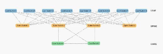
The rest of the answer is to add switches at the layer below the access layer, and then spread the links from the access layer to the next, across the network. This topology is a leaf-spine. A leaf-spine design scales horizontally through the addition of spine switches, which spanning-tree deployments with a traditional three-layer design cannot do.
This is similar to the traditional three-layer design, just with more switches in the spine layer. In a leaf-spine topology, all links are used to forward traffic, often using modern spanning-tree protocol replacements such as Transparent Interconnection of Lots of Links (TRILL) or Shortest Path Bridging (SPB). TRILL and SPB provide forwarding across all available links, while still maintaining a loop-free network topology, similar to routed networks.
The advantages of leaf-spine
Leaf-spine topologies are now the de facto standard -- it's difficult to find a design other than leaf-spine among vendors' various Ethernet fabric designs. There are good reasons for this -- leaf-spine has several desirable characteristics that play into the hands of network designers who need to optimize east-west traffic:
All east-west hosts are equidistant. Leaf-spine widens the access and aggregation layers. A host can talk to another host on any other leaf switch and know that the traffic will only traverse the ingress leaf switch, spine switch and egress leaf switch. As a result, applications running over this network infrastructure will behave predictably, which is a key feature for organizations running multi-tiered Web applications, high-performance computing clusters or high-frequency trading.
Leaf-spine uses all interconnection links. The traditional three-layer design uses spanning-tree, a loop prevention protocol. As mentioned earlier, spanning-tree detects loops, and then block links forming the loop. This means that dual-homed access switches only use one of their two uplinks. Modern alternatives such as SPB and TRILL allow all links between leaf and spine to forward traffic, allowing the network to scale as traffic grows.
It supports fixed configuration switches. Fixed configuration switches ship with a specific number of ports, compared with chassis switches, which feature modular slots that can be filled with line cards to meet port density requirements. Chassis switches tend to be costlycompared to fixed configuration switches. But chassis switches are necessary in traditional three-layer topologies where large numbers of switches from one layer connect to two switches at the next layer. Leaf-spine allows for interconnections to be spread across a large number of spine switches, obviating the need for massive chassis switches in some leaf-spine designs. While chassis switches can be used in the spine layer, many organizations are finding a cost savings in deploying fixed-switch spines.
Leaf-spine is currently the favored design for data center topologies of almost any size. It is predictable, scalable and solves the east-west traffic problem. Any organization whose IT infrastructure is moving towards convergence and high levels of virtualization should evaluate a leaf-spine network topology in their data center.
The cons of leaf-spine
Leaf-spine isn't without shortcomings. One drawback is that the high switch count to gain the required scale. Leaf-spine topologies in the data center need to scale up to the point that they can support the physical hosts that connect to them. The larger the number of leaf switches needed to uplink all of the physical hosts, the wider the spine needs to be to accommodate them.
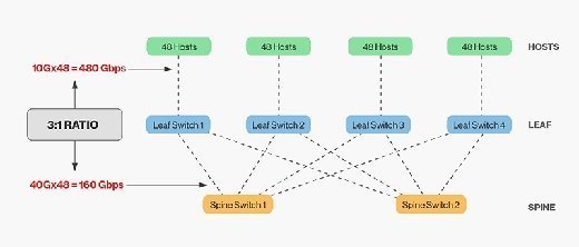
A spine can only extend to a certain point before either the spine switches are out of ports and unable to interconnect more leaf switches, or the oversubscription rate between the leaf and spine layers is unacceptable. In general, a 3:1 oversubscription rate between leaf and spine layer is deemed acceptable. For example, 48 hosts connecting to the leaf layer at 10Gbps use a potential maximum of 480Gbps. If the leaf layer connects to the spine layer using 4 40Gbps uplinks, the interconnect bandwidth is 160Gbps, for an oversubscription ratio of 3:1.
Leaf-spine networks also have significant cabling requirements. The number of cables required between the leaf and spine layer increases with the addition of a spine switch. The wider the spine, the more interconnects are required. The challenge for data center managers is structuring cabling plants to have sufficient fiber optic strands to interconnect the layers. Also, interconnecting switches dozens of meters apart requires expensive optical modules, adding to the overall cost of a leaf-spine deployment. While there are budget-priced copper modules useful for short distances, optical modules are necessary and a significant cost in modern data centers.