Data Center.com
Data center network design moves from tree to leaf
By Ethan Banks
Explained: Leaf-spine data center network architecture
The old data center network design should make like a tree and leaf.
For many years, data center networks have been built in layers that, when diagrammed, suggest a hierarchical tree. As this hierarchy runs up against limitations, a new model is taking its place.
In the hierarchical tree data center, the bottom of the tree is the access layer, where hosts connect to the network.
The middle layer is the aggregation, or distribution, layer, to which the access layer is redundantly connected. The aggregation layer provides connectivity to adjacent access layer switches and data center rows, and in turn to the top of the tree, known as the core.
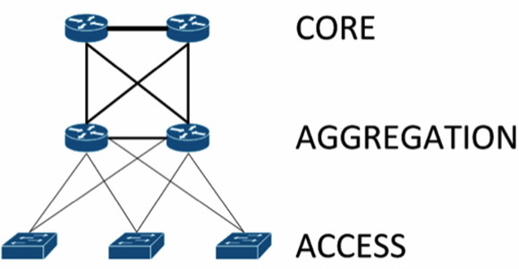
The core layer provides routing services to other parts of the data center, as well as to services outside of the data center such as the Internet, geographically separated data centers and other remote locations.
This model scales somewhat well, but it is subject to bottlenecks if uplinks between layers are oversubscribed. This can come from latency incurred as traffic flows through each layer and from blocking of redundant links (assuming the use of the spanning tree protocol, STP).
Leaf-spine data center architectures
In modern data centers, an alternative to the core/aggregation/access layer network topology has emerged known as leaf-spine. In a leaf-spine architecture, a series of leaf switches form the access layer. These switches are fully meshed to a series of spine switches.
The mesh ensures that access-layer switches are no more than one hop away from one another, minimizing latency and the likelihood of bottlenecks between access-layer switches. When networking vendors speak of an Ethernet fabric, this is generally the sort of topology they have in mind.
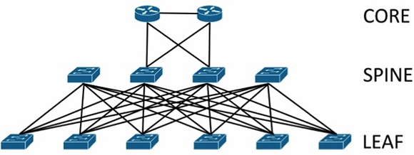
Leaf-spine architectures can be layer 2 or layer 3, meaning that the links between the leaf and spine layer could be either switched or routed. In either design, all links are forwarding; i.e., none of the links are blocked, since STP is replaced by other protocols.
In a layer 2 leaf-spine architecture, spanning-tree is most often replaced with either a version of Transparent Interconnection of Lots of Links (Trill) or Shortest Path Bridging (SPB). Both Trill and SPB learn where all hosts are connected to the fabric and provide a loop-free path to their Ethernet MAC addresses via a shortest path first computation.
Brocade's VCS fabric and Cisco's FabricPath are examples of proprietary implementations of Trill that could be used to build a layer 2 leaf-spine topology. Avaya's Virtual Enterprise Network Architecture can also build a layer 2 leaf-spine but instead implements standardized SPB.
In a layer 3 leaf-spine, each link is a routed link. Open Shortest Path First is often used as the routing protocol to compute paths between leaf and spine switches. A layer 3 leaf-spine works effectively when network virtual local area networks are isolated to individual leaf switches or when a network overlay is employed.
Network overlays such as VXLAN are common in highly virtualized, multi-tenant environments such as those found at Infrastructure as a Service providers. Arista Networks is a proponent of layer 3 leaf-spine designs, providing switches that can also act as VXLAN Tunnel Endpoints.
04 Nov 2013